Crimp Contacts
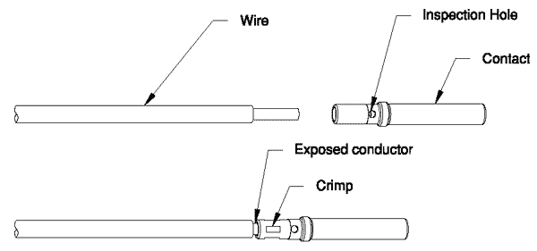
Strip conductor to allow insertion of contact and a .010 to .030 maximum exposure between contact and wire insulation. Insert wire fully into contact, wire should be visible in inspection hole. Center crimp between end of contact and inspection hole. Refer to Chart on page K18 for crimp locator part number.
Solder Cup Contacts

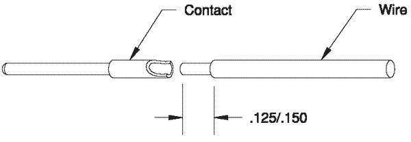
Strip conductor to dimension shown. Tin the conductor. Place a small length of solder in the contact well. Insert tinned wire end into contact. Heat contact to melt solder and position the conductor.

